
 1. Overview
VisualizationSmart lubricationThat is, on the display screen of the lubrication equipment, each lubrication point, each oil supply amount, and cycle interval can be set; fault alarms are displayed; each lubrication point can be automatically supplied with oil, manual supplied with oil, and remote start and stop. All operations can be displayed on the display. On-screen controls and displays. Realize visual control of lubrication equipment. The flow controller of each lubrication point automatically responds to the instructions from the display screen. Serial network communication is used between the flow controller and the display screen operating system to transmit instructions. The oil pressure of the lubrication pump can be set at 10~40MPA. The oil system adopts
Single-line transmission is used, and the lubrication pump and fuel pump are all controlled by electronic control systems.Dry thin oil lubricationAutomatic control, it is an advanced lubrication equipment with mechanical and electrical integration, high automation and network.
Visualized intelligent lubrication equipment has the advantages of easy operation, controllable oil volume, and reliable operation; it does not require on-site manual intervention, one-on-one fault alarms and displays a high degree of automation. Since the crane equipment in the port is very high and has a relatively complex structure, other mechanical systems The lubrication points are also arranged in places that are not easy to maintain, which brings a certain degree of difficulty to the maintenance operations of the lubrication system. If you use intelligent lubrication equipment, you can directly control the lubrication system on the operation screen, and you can directly see the system operating status on the screen. This This is something that ordinary lubrication cannot do. Therefore, intelligent lubrication is widely used in metallurgy, cement, ports, and other industries.
Ordinary lubrication systems cannot see the oil supply status of each bearing on the electric control box. If the equipment fails, the lubrication points will be deoiled and damaged for a long time, causing serious losses or causing excessive oil in some lubrication points to be wasted. Intelligent lubrication adopts a volumetric oil supply method. The system oil supply accuracy is extremely high, and the oil supply amount can be set, the interval can be set, and faults can be alarmed and displayed. The serial bus communication mode is simple and reliable. It is a truly intelligent lubrication equipment.
The main features of smart lubrication are as follows:
1. The amount of oil supplied to each lubrication point can be set arbitrarily on the human-machine operation interface. Good amount of oil.
2. The lubrication time and interval of each lubrication point can be set arbitrarily on the human-machine operation interface.
3. Once the oil passage of a certain lubrication point is blocked or oil does not come out for other reasons, the fault of this point will be displayed on the human-machine interface and an alarm will be issued.
4. The human-machine interface display device with touch screen or Chinese display is used to display the operating status and realize visual operation.
5. Use digital information technology and serial bus communication technology to miniaturize and network the equipment.
6. It adopts a volumetric oil supply control system with high oil supply accuracy.
7. Using one-to-one control of oil supply point by point, the oil pressure is concentrated and high, and it is easy to press it to the bearings.
8. The system uses one lubrication pump and one oil pump.
9. The system uses a microcomputer-controlled file display to visualize the lubrication process.
10. The lubrication system and the central control room are hard-connected by DCS. Centrally controlled start and stop and fault alarm can be realized.
Because intelligent lubrication has the characteristics of visualization, networking, and high automation, it is unmatched by ordinary lubrication. It is a modern lubrication equipment that improves product quality and equipment reliability. It is a good choice for lubrication equipment in port cranes, steel plants, cement plants and other departments.
Because the old ordinary dry oil lubrication system does not have a flow detection system, once the oil line is blocked or oil does not come out, there is no alarm display, resulting in long-term deoiling and burning of the bearings.
Because the amount of oil given in the old ordinary dry oil lubrication system is fixed each time, the amount of oil is too much or too little, causing damage to the bearings or a waste of lubricating oil.
Since there are many non-volume or non-bus-type quasi-intelligent lubrication on the market currently, the non-volume lubrication system uses the control of the opening time of the solenoid valve to achieve oil volume control. Due to the influence of oil line pressure, the oil supply volume error is extremely large. There are also non-bus-type intelligent lubrication that use a large number of cables to achieve switching or parallel communication, making the system complex and prone to failure. Users should consider carefully when choosing to avoid unnecessary losses.
2. System working principle
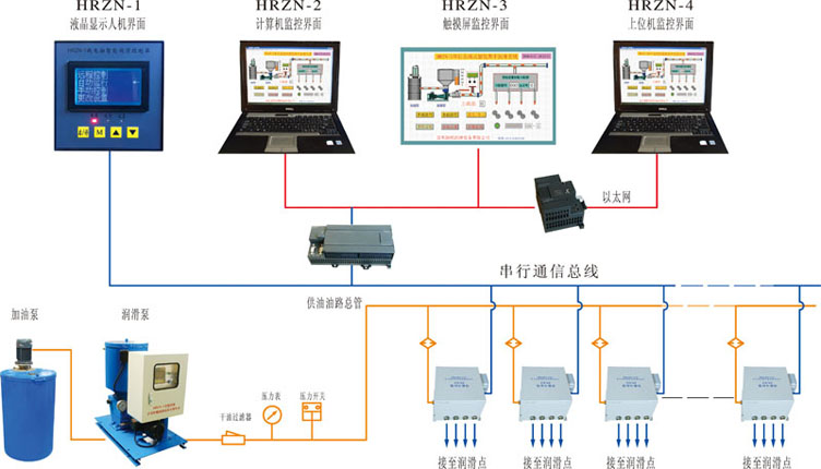
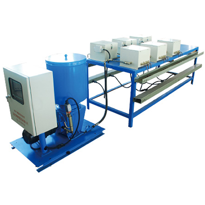
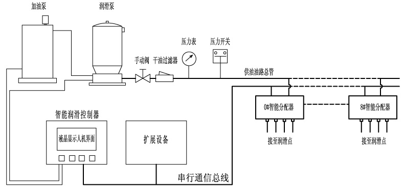
HRZN-1 microcomputer controlled intelligent lubrication system consists of electric lubrication pump, electric fuel pump, electric control box with human-machine interface, electronic flow controller, dry oil filter, pressure switch, oil pipeline, communication bus and other parts.
The electric lubrication pump mainly sends the lubricating oil in the oil barrel to the oil delivery pipe, keeping the pressure in the oil pipe within the range of 10-40Mpa, and providing lubricating oil with a certain pressure to the intelligent distributor. The electronic flow controller automatically supplies oil to the bearings regularly and quantitatively according to the oil volume and interval preset by the user. The lubrication pump has a pressure regulating valve, and the output oil pressure can be adjusted by the user according to actual needs.
The human-machine interface of the intelligent lubrication system can set the oil volume and interval time of each lubrication point. The main menu has four modes: remote control, automatic operation, manual control, and change settings. Users can choose according to their needs.
In the running mode, the electronic control system cyclically supplies oil to each oil point in sequence. First, the electronic control box control system starts the lubrication pump and waits for the pressure switch to act. When the pressure reaches the set value, the pressure switch acts. The electronic flow controller for refueling issues a refueling command. After receiving the command, the corresponding electronic flow controller starts to press oil to the bearing according to the preset oil amount. The human-machine interface displays the oil point number of the bearing. When the refueling at this point is completed, close The fault or normal information returned to the flow controller is displayed on the display, and then the refueling action of the next lubrication point is started. After the refueling is completed, the lubrication pump is turned off, and the display starts counting down the interval. Due to the error in the refueling time of each oil point, the next refueling may not be performed in sequence.
The electronic flow controller is numbered, and the number corresponds to the bearing. The electronic flow controller uses the oil pressure piston to press the grease in the oil chamber into the bearing in a volumetric manner. The accuracy of the oil supply is very high, and the oil line pressure The height does not affect the oiling accuracy.
The work of the electronic flow controller is connected to the electric control box through the communication bus. The control system of the electric control box directs the work of all electronic flow controllers in the form of digital instructions.
The working power supply of the electronic flow controller is AC26V safety voltage. The power of the oil supply valve body is driven by a DC motor. There is a flow detection switch on the valve body. Every time the oil pressure piston moves, the flow detection switch sends out a signal. This signal reflects The flow rate also reflects whether oil is flowing out of the valve body. If there is no signal within the oil supply time, it means that oil is not flowing out, and it is considered a fault. The number of signal pulses during the oil supply time multiplied by the oil volume each time = the total oil volume this time. So the electronic flow controller is the core of the system.
The electric refueling pump is used to replenish grease in the oil storage barrel of the lubrication pump. The barrel is equipped with a liquid level switch. When the oil level in the oil barrel is low, the low liquid level switch point is closed. The refueling pump is started to replenish grease. When the oil level in the oil barrel is low, the electric refueling pump is used to replenish grease. When the liquid level rises to high, the fuel pump is turned off. This process is automatically completed by the control system.
3. How to use
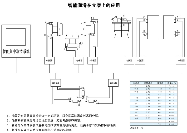
1. The installation of the main oil pipe and the branch pipe of the oil pipe must be neat and beautiful. The inside of the pipe must be kept clean and smooth, and must be kept away from high-temperature baking and low-temperature freezing.
2. The installation location of the lubricating oil pump and electronic flow controller must be protected from wind, snow, rain, sun exposure, strong vibration, high-temperature baking, and low-temperature freezing. The maintenance distance of the equipment must also be considered.
3. The numbers of electronic flow controllers in the same lubrication system cannot overlap. The numbers start from 0 to the end number and can be installed out of sequence.
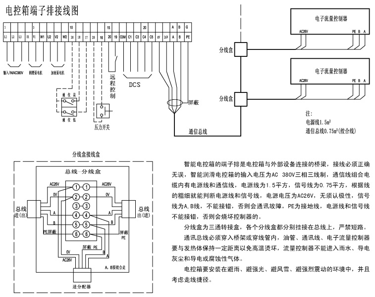
4. The communication combination cable should be placed in a bridge or conduit to avoid high temperature areas. The power cord and communication line in the cable cannot be connected in reverse, otherwise the controller will be burned out. The power cord should be a thicker wire, and the communication line should be a thicker one. Thin wires, the power cord is AC non-polar, and the communication line is divided into two wires, A and B. Do not connect them reversely!
5. The pipelines and circuits of the lubrication system must be wired according to the drawings and must be correct.
6. When using it for the first time, after turning on the power supply, first switch the transfer switch to manually turn on the lubrication pump. After starting the lubrication pump, wait for the pressure on the pressure gauge to rise. If the pressure is not appropriate, you can adjust the pressure regulating valve on the lubrication pump to keep the pressure at The appropriate position and pressure are set according to the oil volume, pipe diameter, length and grease viscosity, and are generally set between 10-30Mpa.
7. After powering on, first set the oil volume and interval time of each lubrication point. For the setting method, see the operation of the display.
8. The central control start-stop lubrication system must use passive dry contacts. The dry contact for the DCS signal sent to the central control room is 24V1A. If the user uses 220V high voltage to add to the contacts, it will easily damage and interfere with the display.
9. Lubricating equipment must have good safety grounding to prevent electric shock.
4. Basic configuration of HRZN-1 intelligent lubrication
Electric lubrication pump HRBZN-D100 0~40Mpa
Electric gas pump HRB-D3.3
Microcomputer display HRZN-1 LCD12864
Electronic flow controller 0#~250# depending on actual needs
Main oil pipe¢18×3 stainless steel pipe
Branch oil pipe¢14×2 stainless steel pipe
Flow controller output oil pipe¢14×2 stainless steel pipe
Power communication line 1.5×2+0.75×2 square millimeter four-core twisted pair shielded cable
5. Configuration of various series
1. HRZN-1 microcomputer controlled LCD12864 liquid crystal screen display monitoring
2. HRZN-2 computer monitoring display
3. HRZN-3 touch screen monitoring display
4. HRZN-4 Ethernet connection to computer monitoring display
6. Main parameters
1. Working pressure 10~40Mpa, set according to the situation
2. The amount of oil given each time is 0~255×0.5ml, which can be set by the user according to needs.
3. The cycle interval time is 0~255×0.5 hours, which can be set by the user according to the needs.
4. The fault alarm display screen displays audible and visual alarms
5. Remote control central start-stop system and fault alarm (DCS connection)
6. Display mode LCD liquid crystal display
7. Bus mode serial bus
8. Input voltage AC 380V three-phase three-wire system
9. Flow controller input voltage AC26V (generated internally)
10. Ambient temperature -20°~50°
11. Ambient humidity 85%
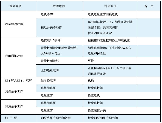
7. Common troubleshooting methods
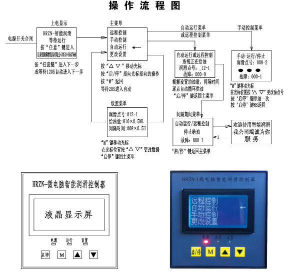
HRZN-1 microcomputer display control is the core controller of the intelligent lubrication system. All functions of the system can be controlled on this human-machine interface.
After the system is powered on, press the "Start/Stop" key to enter the main menu. The main menu contains four items: remote control, automatic control, manual control, and change settings. Press the up and down movement keys to move the arrows to point to different items. When pressed When pressing the "Start/Stop" key, the system automatically executes the project pointed to by the connector.
The oil supply volume and cycle interval time of the system can be set. Just point the arrow to the "Change Settings" item and press the "Start/Stop" button to display the setting menu. The oil volume unit is 0.2ml, and the oil supply volume can be between 0-255. settings between. The time unit is 0.5 hours, and the interval can be set between 0-255. Press the "M" key to move the cursor. The data at the cursor position can be modified with the "increase" and "decrease" keys. Before using the system, the parameters of each oil point must be set first. The oil point number with an oil quantity of 0 is regarded as closed and does not supply oil.
Automatic operation: After starting the automatic operation, the system automatically supplies oil point by point according to the set parameters. Since the parameters of each oil point are not equal, the order of oil supply is not necessarily sequential. During the oil supply process, if no oil flow signal or communication error is detected, the system will briefly alarm and display the faulty oil point number. The system will cycle through the alarm fault point number during the interval. If the fault point has been eliminated during the next oil supply, then The system no longer alarms and displays the original fault point. Automatic operation without manual supervision.
Manual control: In the manual control state, manual oiling can be performed on the oil point number on the current screen. As long as the "Start/Stop" key is pressed, the system will oil the preset oil amount once. After the oiling is completed, it must be pressed again. "Start/Stop" key returns. The oil point number will automatically increase by one and wait for continued refueling.
Remote control: After executing the remote control command, the system sends a ready signal to the central control room. After the remote drive dry contact in the central control room is closed, the system enters automatic operation. If the remote drive is disconnected during the oil supply, the system will complete the oil supply at all points. Then stop running and wait for the drive signal to close again before continuing to run.
The total number of flow controllers built into the display must match the actual installed number. Otherwise it will not run properly.
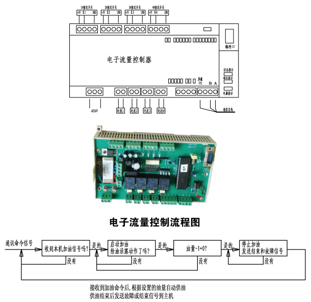
Electronic flow controller is composed of valve body, drive motor, detection switch, control circuit and other parts.
The valve body is an assembly of a positive displacement oil feed body. It is driven by a DC motor. The piston in the valve body is driven by the oil pressure to send a certain amount of lubricating oil pressure in the cavity to the bearing. The number of piston movements is multiplied by each time. The amount of oil is the total amount of oil supplied. The detection element detects the number of movements of the piston to determine the amount of oil. If the oil path is blocked, the piston will not move. If the detection element cannot detect the action signal, it will be regarded as a fault, and a fault will occur by the control. Call the police.
The electronic circuit is controlled by a single-chip microcomputer, which controls the work of the control valve body and the data communication with the main controller. After receiving the refueling command from the main controller, it starts the valve body to supply oil. After the oil supply is completed, it sends an oil supply status instruction to the main controller. , this command includes fault information.
Each electronic flow controller has a fixed number. The numbers in the same system are sequential and do not overlap. The numbers start from 0. For example, 000-2 represents the second point of controller No. 0. Each number corresponds to each bearings.
The electronic flow controller is connected to the AC26V power supply, communication lines A, B, PE, motor, and flow detection switch. Wire according to the drawing. If the indicator light on the detection switch flashes during oil supply, it is normal. If it does not flash, it is a fault. It is not supplying oil. It may come on or off indefinitely.
Rainwater, conductive dust and conductive gas cannot enter the electronic flow controller. Cannot operate in an environment higher than 50°.
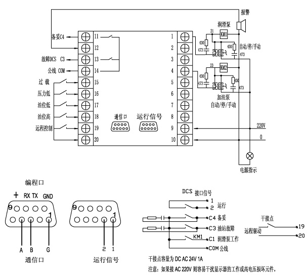
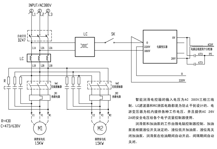
The microcomputer controller in the intelligent lubrication electronic control box is the core component of the lubrication system. It is connected to the lubrication pump, fuel pump, liquid level switch, pressure switch, flow controller and DCS in the central control room.
The system's lubrication pump and fuel pump can be started automatically, stopped or manually, and are selected by a transfer switch. In automatic mode, it is controlled by the system, and the oil pump starts directly in the open position.
The system has a serial bus communication port, which forms master and slave serial communications with each electronic flow controller. Each electronic flow controller implements functions such as timing and quantitative oil supply, fault alarm, etc. in the form of instructions from the main controller.
The system is connected to the user's central control room using a DCS connection. The system provides operation, readiness, failure, and lubrication pump working signals to the central control room, and the central control room can use a pair of dry contact signals to control the work and stop of the lubrication system.
1. Main screen - automatic operation
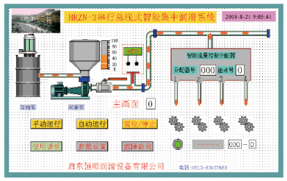
The main screen and the automatic running screen are combined into one screen. There are six buttons on the screen: automatic running, manual running, reset and stop, parameter setting, fault query, and instructions for use. As long as a button is touched, the system will enter the function described by the button. .
The automatic operation screen uses graphic animation to simulate the operating status of the lubrication system to achieve visual lubrication and intelligent lubrication.
As long as the power switch of the lubrication equipment is turned on, the main screen of the automatic operation will be displayed on the screen. As long as the automatic operation button is touched, the system will start to run automatically. On the automatic operation screen, there are graphics and data such as fuel pump, lubrication pump, oil level gauge, pressure switch, oil pipe supervisor, intelligent flow control distributor, fault display, alarm, etc. After the system is started, the lubrication pump starts to supply oil, and the lubricating oil in the oil pipe begins to flow. When the pressure switch is closed, the intelligent flow control distributor starts to supply oil. The distributor number and oil point number that are supplying oil are displayed in the graph of the distributor. , at the same time, the animation of lubricating oil at the outlet of the distributor drips onto the user's gear. If a certain point fails and no oil is released, the alarm indicator light will light up, and the alarmed oil point number will be displayed in the alarm data box. The oil supply amount and interval time of each oil point are executed according to the set value. The system automatically performs refueling according to the oil supply amount and interval time set by the user. If you want to stop refueling, you can touch the stop button.
The system refuels the lubrication points point by point, and the pressure is concentrated for rapid refueling.
The system automatically cyclically refuels the lubrication points without manual intervention.
2. Manual operation
The graphics on the manual operation screen are the same as those on the automatic operation screen. First, start the lubrication pump manually, then enter the distributor number and oil point number. Touch the manual refueling button and the system will perform refueling at that point. After refueling, the oil point number will automatically increase by one. , the fuel pump can also be started and stopped manually.

3. Operation during interval
After the system has refueled all lubrication points, it will enter interval operation, turn off the lubrication pump, display the interval operation screen, and wait for the next lubrication. If the interval countdown ends at a certain point, a new round of lubrication will begin. The system works in cycles over and over again.
4. Parameter settings
On the parameter setting screen, first set the total number of distributors in the system, and then set the distributor number. Each distributor has 4 oil outlets. The oil volume and interval of each oil point can be set independently. You can read the original data before setting. If the original data does not need to be changed, you can set the next distributor. The distributor number can be entered directly or set gradually by pressing the "+-" key. To input data, you can touch the numbers in the data box, and a soft keyboard will automatically pop up. Just enter and confirm the data on the soft keyboard.
All oil point data must be saved after being set and will not be lost.

5. Fault information query
In the fault information column, you can check the fault oil point number and fault occurrence time, and you can also clear the fault information.
Pay special attention to setting the date and time first after powering on the system, otherwise the time when the fault occurs will be different from the actual time.
The system date and time will disappear after a power outage, so they must be reset after power on.
6. Instructions for use
There is a terminal block wiring diagram on the instruction manual screen, so you cannot make wrong connections.

Address: No. 010, Xinglong Road, Huilong Industrial Park, Qidong City
Sales hotline: 0513-83637668
Company fax: 0513-83637098
After-sales service: 0513-83635700
Website: delcan.cn
E-mail:qd3637668@163.com

Scan to learn more